- Inicio
- >
- Noticias
- >
- Noticias de la Industria
- >
- The P-type and N-type of a Diode
The P-type and N-type of a Diode
A diode is an electronics component made from a combination of a P-type and N-type semiconductor material, known as a p-n junction, with leads attached to the two ends. These leads allow you to easily incorporate the diode into your electronic circuits.
The lead attached to the n-type semiconductor is called the cathode. Thus, the cathode is the negative side of the diode. The positive side of the diode — that is, the lead attached to the p-type semiconductor — is called the anode.
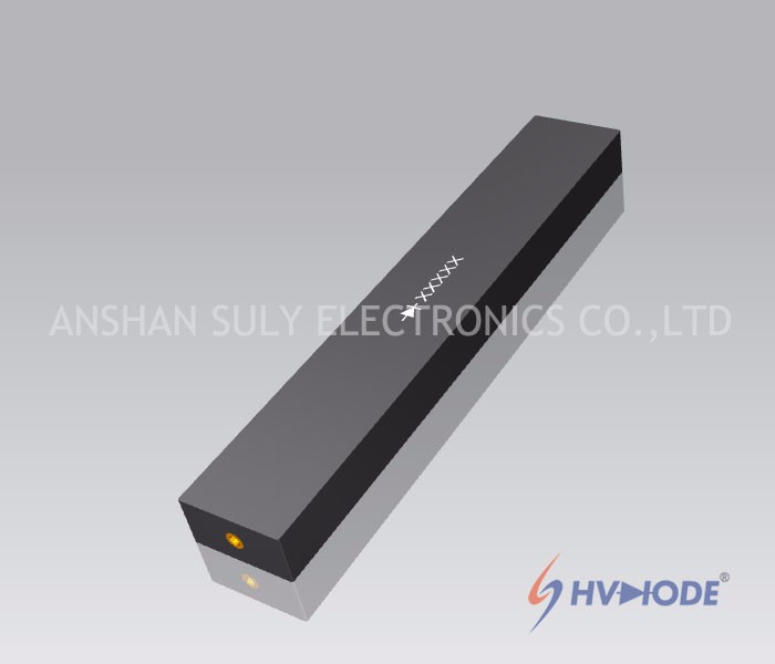
When a voltage source is connected to a diode such that the positive side of the voltage source is on the anode and the negative side is on the cathode, the diode becomes a conductor and allows current to flow. Voltage connected to the diode in this direction is called forward bias.
But if you reverse the voltage direction, applying the positive side to the cathode and the negative side to the anode, current doesn’t flow. In effect, the diode becomes an insulator. Voltage connected to the diode in this direction is called reverse bias.
This is the symbol for a diode :
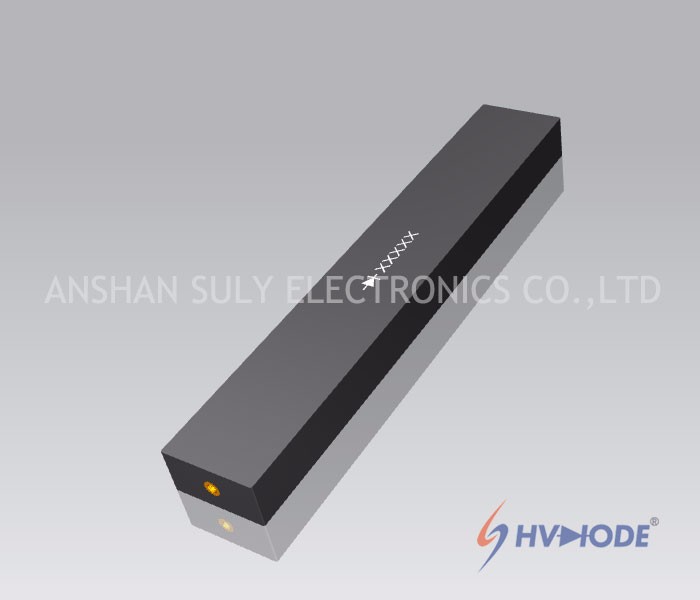
Electronic circuits are designed to work with other circuits to form a unit which completes a designated task. Many circuits, such as power regulation circuits, need to be protected from power "spikes" and accidental polarity reversal. The diode is one of electronic components that only permits electricity to flow in one direction while preventing potentially harmful reversals from reaching the sensitive circuit. The electricity flows into the "cathode" (negative side) of the diode and then out the "anode" (positive side) toward the protected circuit. Knowledge of electronics standards is a must when installing a diode.
So,how to obtain the schematic diagram for the circuit?
The vertical line represents the cathode of the diode. That end of the diode must face the direction from which the negative current flow is coming.
Look at your diode closely, using a magnifying glass if necessary. Every diode has either a colored dot or a band printed on the cathode (negative) end of the component. Black plastic diodes will have a white band painted on the cathode end and glass diodes will have either a white or a black band.
Use a digital multimeter to test the polarity of a diode in the event the polarity markings are absent or missing. Simply turn the meter unit on and turn the dial to measure "Ohms." Hold the black (negative) test probe to one metal leg of the diode and the red (positive) test probe to the other metal leg. If you see no reading, or just a "1" displaying on the meter, reverse the probes. When you get an actual reading in ohms on the display, note the side the negative (black) probe is on. That is the cathode (negative) side of the diode.
That is the most simple way to recognize the diode ,especially the high voltage diode ,like our products.
Written by lisa


